New Free Tutorial Series! by Jeremy Ernst

I’ve released a new tutorial series on YouTube that covers my skinning workflow in Autodesk Maya and a bunch of Unreal Engine 5 information, including setting up the character, retargeting animations, setting up cloth simulations and other procedural dynamics, and more. Hope folks find this useful!

Preview of the final result of the tutorial series.

Check out the full series here:

Tutorial: Retopo for Skinning by Jeremy Ernst

Learning how to retopologize a model to make skinning easier was not something I started doing until later in my career, which is unfortunate because it can be such a time saver!

In this quick video tutorial, I’ll go over the basics of Maya’s retopology tools and how you can use retopology to build yourself a mesh that is quicker and easier to skin weight, then transfer those weights over.

Note: There are many methods of transferring skin weights. I personally like the utility found in Zoo Tools, because it is easiest in that I do not have to create a skinCluster before copying weights. That said, if you want to stick with the tools Maya provides, there are plenty of options available.

[Tutorial] Reference Grouping Tool by Jeremy Ernst

I had someone ask me about how to go about creating a tool that would allow you to group references to unload/load with one click, any references in that group. This person was looking to learn a bit more python, so I recorded my process as I built the tool.

The recordings are not edited, so I do stumble through some parts, and the code is probably not as clean as it could be. (Also used my shitty headset mic instead of my good setup, sorry about that).

This is what the final result looks like. Each object is a referenced file. Those references can be added to groups, and all references in a group can be loaded or unloaded with a click.

Below are the video recordings of me building the tool.

Full script:

[Tutorial] Adding Geometry to Existing Blendshapes by Jeremy Ernst

I had a question recently about a situation where a bunch of blendshapes were made, and now hair cards needed to be added to the mesh, and if it was possible to retain all of those blendshapes and add that new geometry.

The answer is yes!

So here is a simple example where we have a head and we have a blendshape that opens the mouth.

Now, some hair cards get added and we want those to deform with our blendshapes and be attached to the mesh (Assuming this is a realtime application where wraps wouldn’t be applicable).

In this case, we need that new beard geometry to deform with the blendshape. Rather than use a wrap, I’m going to create a skin cluster here instead so I can paint the weights. In this gif below, I create a joint, simply to get a skinCluster going and bind the beard to the joint. I then add the head mesh as an influence to the skinCluster, making sure Use Geometry is checked. Now, in the skinCluster, I can turn on UseComponents, and the mesh will deform the beard, much like a wrap, except now we can actually tweak the weighting of that deformation.

Here, I can tweak the weights of that deformation so the mustache area isn’t stretching.

Here are the steps of what’s happening in the gif below to get our new geometry added and deformed to our blendshapes:

(If you have a lot of blendshapes, scripting this would be ideal). For each blendshape, the process would be:

  • Move each blendshape mesh back on top of your main mesh.

  • Turn that blendshape on

  • Duplicate the beard geometry as it gets deformed by the blendshape

  • select the duplicated geometry and the blendshape mesh and combine. The combination order must be the same on every mesh. In this case, I will always select the beard, then the head, then hit combine.

  • Don’t delete history yet until all blendshapes are done. Rename the new combined mesh.

Once that is done and you have combined meshes for all your shapes, delete history on them, then do the same combination on the main mesh and the beard there (selecting in the same order as before, beard then head). Now when I hook my blendshapes back up, the new geometry is attached and nothing is deforming oddly.

That’s it!

Introducing Project Horror by Jeremy Ernst

Just a heads up, There is some violence/gore in some of these videos. Viewer discretion advised!

The very first screenshot I took. At this point, I was using some marketplace assets for the level and Advanced Locomotion System for the player.

The very first screenshot I took. At this point, I was using some marketplace assets for the level and Advanced Locomotion System for the player.

On June 29, 2020, I started a side project deemed Project Horror. I wanted to make a vertical slice of a survival horror game. There were a few reasons. First, I wanted to learn some new things within UE4 that I don’t typically get to interact with during my day job. Secondly, I just wanted to see if I could make a complete game experience. This is still work-in-progress, but I figured I’d start some posts chronicling my progress.


One of the first things I worked on was an inventory system. I was familiar with UMG, but wanted to expand my knowledge here, so I started building out the necessary classes for the inventory system and then the UI elements.

After I got the initial system setup, I added looting, added doors/keys, and inspect, a throw-back to Resident Evil games.


After I got the inventory sorted, it was time to start work on AI, which is another area I did not have much experience in.

After getting some basic AI in, it was time to tackle gore! Gore is fun (that’s a normal thing to say, right?) because it presents some interesting challenges. I had worked on gore stuff on previous projects (Gears series, Condemend 2) and it can be pretty difficult to get it looking decent. First, I turned off the AI in this test and just wanted to get some basic limb dismemberment happening, as well as spawning some VFX.

With gore implementation, also came implementing enemy health. The next step was to integrate back in the AI and add some additional details, like blood trails.

After I got that working well, I swapped the model for a zombie cop I snagged of CG Trader I believe. I re-rigged it (I think it came with a skeleton) and modified it so I could have it come apart. I also added a stomp move the player could do to finish off a downed enemy.

I picked up a player model, also from CG Trader, rigged it up, and started working on custom animations, which is something I am NOT terribly good at.

I had experience doing relatively simple anim graphs, but I wanted to try and do some things I didn’t have experience with. This test involved having different holster states depending on time passed during certain actions. If the player wasn’t aiming, the gun would be lowered. If the player was in the lowered state for a bit, the gun would then be holstered.

Then I started trying to figure out what the narrative might be for this complete game experience and building up a level to support that. I also picked up some new zombie models that I’ve not yet rigged up, but are shown in the video below. The environment assets are mostly picked up from the Unreal Marketplace. I don’t even want to know how much money I’ve spent on assets from the marketplace (Sounds, environment assets, VFX).

That’s all for now. I’ve been continuing work on the level layout, the player (been learning xgen so I can do a groom and have simulated hair), the player’s face rig, and more zombies/rigs. This brings us up to about a year and some change to get to this point, working pretty light hours, to be honest. I actually haven’t touched it in a few weeks, but am looking forward to getting back to it.

Stylized Face Rig Practice by Jeremy Ernst

I signed up for CG Master Academy’s Facial Rigging Course so I’d have something to hold me accountable to doing another face rig, since they can be quite tedious. I went with a stylized model, which I picked up off CG Trader.

I should definitely have put more time and effort into making the pose tests, but I got bored. I don’t think I had the fleshy eyelids implemented at this point either.

I should definitely have put more time and effort into making the pose tests, but I got bored. I don’t think I had the fleshy eyelids implemented at this point either.

The face rig uses a combination of blendshapes, joints, and deformation layering. The two new things I picked up were the method for “smart blink”, where the blink line remains clean regardless of the eyelid poses. The other thing was space switching for the upper lip, which required having a main joint for the upper lip that any other upper lip joints would be parented under, then setting up spaces on that main upper lip joint to either follow the head or the jaw.

I learned how to use Mudbox, so I could sculpt the shapes needed. Also messed around with Arnold to render some of the poses out. I did a quick mocap test using my iPhone and the MocapX app. It did alright, but out of the box, is quite stiff, almost like stop motion. I could probably have iterated more on the poses it wanted as well, but I didn’t want to spend too much time on it.

Joint-Based Muscle Setup by Jeremy Ernst

I wanted to test out a simple solution for adding more volume preservation and movement using just joints and a simple squash/stretch segment setup. The idea was to place joint segments where the muscle would tend to sit, then utilize a single chain IK solver combined with squash and stretch on the base joint to get volume preservation.

For example, the pectoral muscle attaches along the sternum/clavicles, and inserts itself near the bicep.

pectoral.jfif

Because we’re dealing with a simplified skeleton, the joint segment is going to be parented under the relevant spine joint, with the end of the segment landing somewhere on the upper arm. (In my quick test, I didn’t place it super accurately to the muscle, but the desired result is achieved regardless). The script (posted below) will create the setup and parent the IK handle under the insertion parent, the upper arm in this case.

Combined with using NgSkinTools, this was a really quick way of achieving some decent joint-based volume preservation.

This was the simple script I wrote to setup the stretchy segments for the muscles:

The final result:

Personal Project: Cartoony Witch Face Rig by Jeremy Ernst

I’ve been working on a survival horror game in my free time, but during the month of October, I wanted to switch gears and try to make a cartoony face rig. I first watched Josh Sobel’s Expressive Facial Rigging, and then worked out how I could apply some of those concepts in a more game engine friendly manner. (Hint: it’s just lots of joints and corrective shapes). Unfortunately, aside from using Alembic exports, the whole global/local rig concepts in the tutorials isn’t really applicable to game engine workflows.

I’m probably about 50% happy with the end result. There is a lot more I’d like to have done, but I set myself a time limit as to not spend forever on it, so maybe the next one will go a bit faster.

The rig is mostly joint-driven with about 20 corrective blend shapes. I also threw some quick dynamics on the hair and hat in UE4, but they’re not very polished.

Here it is rendered in UE4:


And here it is in Maya:


Refactoring Part 5: Component Settings Widget by Jeremy Ernst

In the beta version of the tools, in order to change settings on a component, a settings widget needed to be built. This widget was written each time for each component. Even worse, it was impossible to do anything without a graphical user interface. You could not change a property on a component via command line, it had to be done through a UI. It. was. bad. You can see in the instantiation of the leg class, that it even took in the instance of the user interface! These two things should be totally separated and a component should never need to know about the user interface!

What the hell was I thinking?

What the hell was I thinking?

In order to address this, obviously things were rethought from the ground up. This is covered in previous posts, but to summarize, a component creates a network node. It uses properties to get and set data on the network node. The UI simply displays that data or calls on the setter for a property if a widget value is changed. You can see the general flow of this below.

Components are instantiated by either passing in no network node, in which case one is created, or if a network node is passed in, you create an instance with that data. You can see an example of that here:

Properties are an important element in this refactor. In order to have a component’s settings widget auto-generate, it simply gathers the properties of that class (including the inherited properties) and builds a widget off of those. By looking at the corresponding attribute types on the network node, it knows what type of widget to build. And because it’s a property, the changing of a widget value just calls on setattr! Here is what the code looks like for generating the property widgets and setting a property:

Okay, so let’s look at this in action. The UI has been redesigned to be faster and easier to use. In the clip below, when the Rig Builder is launched, it will create an asset and a root component. Then components can be added to the scene, which will add them to a list widget. Each item in the list widget has icons next to them for hiding that component in the scene, toggling aim mode, and toggling pin-in-place. Clicking on an item builds the settings widget for that component, which is generated from the component’s properties. Any changes to those settings then call on the component property’s setter, which handles what happens when a value is changed.

Since these changes, writing tools for the components has been a breeze. It’s amazing what a difference a good design can have on development efficiency. I’ll go over the Rig Builder interface and its various tools next time.

Refactoring Part 4: Component Creation by Jeremy Ernst

It’s been a while since I’ve posted an update on the progress of the tools. I’m pretty happy with where things are right now where they’re headed. I figured I’d make a post comparing the differences of creating a new component in the beta version of the tools to the new version of the tools.

In the beta version, a fair amount of code needed to be written and a fairly complex maya file had to be created before you could have a component that could generate some joints. This was frankly due to bad design and a lack of forethought and planning.

The highlighted methods were ones that needed to be implemented in this case, for the leg to work and generate joints.

The joint mover file was also complex and had some assumptions about hierarchy and naming. All bad.

There’s a lot to address here. For instance, the class for a component should be much simplified and should not need to be building UI widgets and such. Lots of the bespoke functionality was because of a lack of a unified system, so each component might have its own way of pinning a component, or setting up aim mode, or whatever.

Here’s a class diagram of the refactored code.

There’s a lot to look at, but the important bit is BipedLeg and how little is needed to get that component creating some joints. To create a component, you simply need to define the unique properties of that component (ex: number of thigh twists) by adding them as attributes to the metanode and then implementing their property getters and setters. You also need to define/create a joint mover file, which is now incredibly easy.

For the new joint mover file, you start by creating the joints you want your component to have in its max configuration (there are exceptions to this like the spine and chain which you actually create the min configuration).

Create the joints you want your component to create, and give them a name (which the user can then overwrite if they wish).

Once you’ve created your joints and ensured your joint orients are nice and tidy, there is a tool to mark the joints up with attributes. These attributes will build the joint mover controls, determine how aim mode is setup, etc. Once you’ve set the attributes, save the file, set the class attribute for the path, and you’re good to go!

Mark up joints with attributes to determine the control shape that will be applied, if the joint aims at another joint, the aim details and so on.

With these changes, creating new components in the refactored code is incredibly easy and quick. I’m sure there are things that could still be better, but it’s definitely a marked improvement from where things were. So far, there are 11 components in the ARTv2 refactor. Some of the previous components like arm, have been broken down into arm and finger.

The components in the ARTv2 refactor build.

The components in the ARTv2 refactor build.

Creating a component instance brings in the joint mover file, then builds a joint mover on top of the joints according to the markup data.

In the next post, I’ll go into the new user interfaces and how the refactor helps automate widget creation for components.

UE4 Layered Clothing Test by Jeremy Ernst

I was working on making some ARTv2 rigging tutorials using this model (how to rig a custom asset), but got distracted and decided to get it in UE4 and play around with getting the layered clothing looking okay. Trying to get clothing not to clip into everything can be challenging, and this mesh had lots of layered bits that all needed to collide properly. It’s not 100% perfect, but good enough for the time put into it. I wanted to do more, like add more dynamics to the hair and such, but I figured I should get back to actually making those tutorials I set out to make in the first place!

Refactoring Part 3: Proxy Model Maker by Jeremy Ernst

In the last post, you saw a glimpse of what one of the refactored components looks like, but you may have noticed that the proxy geo that comes with the components in the ARTv2 beta version was missing. One of the things I wanted to do when doing this refactor was simplify and separate responsibilities. The joint mover was doing too much. It was responsible not only for placing joints, but for defining the proxy geometry. This made the class huge and also made the joint mover carry around lots of baggage that was really only needed at the very beginning of the process.

ARTv2_leg_component.PNG

Also, some people may not even want or need the proxy geometry. They may just want to simply place a component’s joints and not have to worry about or fuss with that step. So, I decided to remove it from the component and separate it into its own tool. This way, people that want to use proxy geometry still can, but it is not included with the components.

At work, we use proxy geo extensively. It lets us get characters in game with only a rough concept sketch and validate and iterate on proportions and height quickly. This also provides a template for the modelers to build the final asset from. We wanted to add more features to the proxy geo to be able to validate form, which the current ARTv2 beta setup was too clunky to do. It was at this time, that I decided to separate out proxy geo from components and add more features to the proxy geo in order to get better results that would allow validation and iteration on proportions, form, and scale.

Basic shaping in the Proxy Model Maker tool

The stand-alone tool (meaning it can be used outside of ARTv2 altogether), is setup in a similar fashion to the ARTv2 refactor, meaning it is component-based. For every ARTv2 component, there will likely be a matching proxy model maker component. As you can see in the above video, proxy geo components are no longer segmented. There is a simple “rig” that allows for some basic shaping.

In the component settings, you will see that there are sliders for the physique. These allow some basic detailing to rough in the form of the body.

Furthermore, there are shaper controls that can be used to further shape a component. These shaper controls support local mirroring (mirroring within the component).

Some components, like arms and legs, can be mirrored. Settings from any component can be copy/pasted to similar components, and transforms can be mirrored across components like arms and legs.

Settings, Transforms, and Shaper values can be copy/pasted and mirrored.

Settings, Transforms, and Shaper values can be copy/pasted and mirrored.

Some components can be mirrored.

Some components can be mirrored.

So, in short, that’s what I’ve been working on (albeit, not a ton as other work-related tasks have popped up!). To be honest, while I know it’s a marked improvement over what was there initially, I still think it might be a bit limited compared to something like CG Monastery’s MRS, in terms of this catering more to a semi-realistic style. I also really like their lofted setup. For my shapers, I’m using wire deformers, which I think works well enough.

As you can see in the UI, the output of this tool will be a single mesh without all these deformers that can then be rigged and skinned. Now, if you use ARTv2, the plan is that this will be automated (it will know where joint placement should go based on the mesh and should know how to skin it based on your ARTv2 component settings). This work hasn’t been completed yet, and I still need to do the head component, prop components (single joints), chain components (tails, tentacles, etc), and the export mesh feature. If you don’t use ARTv2, then the plan is to have the hooks there so you can automate that with your own stuff. Oh, also, all the meshes are already unwrapped, so you can paint a quick texture on there for color-blocking your proxy. Part of the plan for the export mesh function is to take the UVs and combine them onto a single set.

UVs.PNG

Lastly, here’s a demo of what I have so far:

If anyone is interested, I can go over the code stuff in a follow-up post. Let me know what you think, as I think this is a good direction, but honestly, I’m just winging it.

Refactoring Part 2: Basics by Jeremy Ernst

I didn’t mean for two months to pass between these posts, but c’est la vie. The last post went over some high level concepts of refactoring. In this post, I’ll start to show how the concepts are being applied to ARTv2. Let’s start with the base component class. This is an abstract base class that all components inherit from.

Abstract classes may not be instantiated, and require subclasses to provide implementations for the abstract methods

The original (currently available) version of ARTv2, the base class was huge. It did way too much and was too cumbersome to sort through and debug issues. One of the goals for the refactor was to do a better job simplifying classes and their responsibilities. Below is the current state of the base class.

new_base_class.PNG

The base class contains the bare minimum amount of common functions and a few necessary properties. Properties are being used to handle lots of functionality when modifying aspects of a component. In the previous post, I mentioned how many ways I had implemented setting a parent of a module. This is now done via a property on the abstract base class.

For those that don’t know about properties, they’re essentially class attributes that contain functionality. There are plenty of good articles out there explaining them, like this one. Take for example, the property parent. If I want to know a component’s parent bone, I can call inst.parent, which will use the getter function of the property decorator to return the parent bone. This functionality of how that info is returned in defined in the property, like this:

This is just returning the attribute value on the metanode (more on that later). If I want to set or change the parent of this component, I can do inst.parent = “new_bone”. This will call on the setter of the property, which contains a little more functionality.

Compared to how I was doing this before, this is a significantly cleaner way to handle getting and setting the parent bone of a component. You may notice the setter calls on some extra functionality. This line in particular is of interest:

In order to separate out responsibilities, I’ve been using composition.

Composition means that an object knows another object, and explicitly delegates some tasks to it.

At the beginning of the base component class, the following code is executed:

The last two lines are an example of composition. An instance of a class is assigned to a class attribute, which then delegates functionality to that class. So rather than include all the joint mover functionality in the base class, it gets separated out into its own class that only handles joint mover functions. Then the base class can call upon that JointMover class to execute functions related to joint movers. (In this case, adding the joint mover for this component to the scene). An important thing to note here, is that the ART_Component knows about JointMover, but JointMover does not need to know anything about ART_Component. It is given all the information it needs on instantiation (which is the joint mover maya file and the metanode that contains all the metadata it needs).

To finish this post, I’ll talk about the metadata/metanodes. While the current version of the tools utilizes these, it does not nearly utilize them enough. Probably because I didn’t fully grasp how to properly utilize them. First, they (in my refactored implementation) are a huge part of the component’s class. Any information the class returns when asked is going to be pulled off the metanode. Anytime data is changed, it is on the metanode. The properties mentioned earlier, are essentially getting and setting metanode data as well as doing the extra needed functionality.

For example, when setting a parent for a component, one of the first things it does if the parent is valid, is set that data on the metanode.

When returning the parent, it returns the data from the metanode. Why does this matter? Well, the biggest reason is that it makes it incredibly easy to make an instance of a component to get access to its functionality when you have a way of supplying all of the information an instance of the class would need.

In the ARTv2 beta, I actually do not have a great way of getting instances of classes to access functionality. If I want to call on a component’s buildRig method, I do all this extra work to build up an instance of that class in order to do so. Now, a component can be instantiated with a metanode, which it will then use to populate its properties.

Furthermore, everything can be done via a command line now. Embarrassingly, this was not the case in ARTv2 beta. So much of the functionality was only accessible through the user interface. Here is an example of some of these concepts in action:

Creating a root and leg, and setting some properties on the leg.

Creating a root and leg, and setting some properties on the leg.

Accessing an instance of a component by passing in its metanode.

Accessing an instance of a component by passing in its metanode.

One thing you might notice is that proxy geometry is gone. More on that next time!

Refactoring Part 1: Concepts by Jeremy Ernst

I wanted to write some posts about refactoring ARTv2 as I go through it. Personally, I’ve learned a lot developing these tools over the last few years. When I started writing these tools, I had a very different outlook on writing code. This had a lot to do with the incredibly fast-paced production environment I was in. I definitely looked at code as a means to an end, and if it “worked”, it was done.

Depending on the tool or the scope of the tool, this might be fine. When I start thinking about our industry though, where most of us are working on games that are considered services, a successful game (League of Legends, Fortnite, World of Warcraft, etc) could span 10+ years. And when you start thinking about the tools and pipeline you are using now, and being stuck with it in 10+ years because your project is still successful, you’ll probably wish you would have put more effort and thought into your code.

The neat thing about where ARTv2 is now, is that it is much easier to look at the big picture and see where things can be fixed and cleaned up. When I first started writing it, I didn’t really have a big picture in mind. I’d develop a feature, then think of the next feature, and develop it. This led to lots of giant files with lots of duplication. So, now I’ll talk about what refactoring is for anyone that doesn’t know, and why it’s important.

Code refactoring is the process of restructuring existing computer code—changing the factoring—without changing its external behavior.

When you tell your producers or lead that, it can be hard to sell them on the idea that this is a valuable endeavor. So, I actually made a slide deck going over the benefits of refactoring and giving some examples. I’ll start with a completely true example that came from ARTv2.

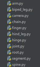
I was working on a character and a bug presented itself where joint and chain modules weren’t being parented correctly. I tracked it down and implemented a fix. A couple days later, I change the parent on one of those modules to a different joint, and the bug pops up again. I track it down and find that I had duplicated that parenting code into the change parent method. So I fix it again. Some time later, I go to create a mirror of a module, and sure enough, the bug pops up again. It also popped up when loading a template. There were four separate places where the parenting code was implemented. And this comes from the way I thought about code before.

By implementing things on a feature-to-feature approach, each feature was built as a complete tool. Each feature would have code duplicated throughout with little regard to re-use or sharing common functions. Did the code work? Sure. But as the above example points out, it makes tracking down and fixing bugs a massive pain (and it’s just sloppy). When I ran into that same bug over and over, I realized that maybe I should do a pass and clean things up.

However, as I looked into it more, I realized I should just take this opportunity to really think things out and to also write unit tests as I went. If you don’t know what a unit test is, it’s basically code you write that tests code you’ve written :) A quick example would be if you had a function that took in an integer and added two to it. Your test would then call on that function with different inputs and maybe different types of inputs, and assert that your output assumptions are correct.

import unittest

def example_func(value):
    return value + 2

class MyTest(unittest.TestCase):

        def test_simple(self):
          self.assertEquals(example_func(2), 4)
          self.assertEquals(example_func(0), 2)
          self.assertEquals(example_func(-2), 0)

          # here, we know this should fail, since we haven't added anything to deal with strings. 
          with self.assertRaises(TypeError):
              self.assertEquals(example_func("one"), 2)

        def runTest(self):
            self.test_simple()

test = MyTest()
test.runTest()

This is a super simple example, but hopefully it illustrates what a unit test does. If you know that each of your methods has a test, it becomes very easy to isolate problems and ensure problems don’t arise in the future.

Moving on, these are the main reasons for refactoring ARTv2:

  • Remove Duplication

  • Simplify Design

  • Add Automated Testing

  • Improve Extensibility

  • Separate Form and Function (UI from functionality)

I’ve talked about the first and third, so let me quickly explain the second using the duplication example. That implementation was something akin to this:

duplication_example.jpg

A better implementation would be something like below, where each of those tools simply calls upon the module’s set_parent() method. This approach not only removes duplication, but simplifies the design. Any user who wants to set the parent on a module can probably guess correctly that such a method exists on the module class.

simplify_example.jpg

It all seems so very obvious now, but when I first started out writing this, my mind just didn’t think about the design of code at all. Being self-taught likely means I skipped over a ton of the basics that most programmers just know.

Lastly, extensibility. (Is that a word? Spellchecker seems to think not) Basically, this is designing your code in such a way that if the parameters or requirements change, code modifications are minimal. Here’s an example of that:

Here, we have an exporter that has a monolithic method for exporting bone animation, morph targets, and custom curves. Later, we now need to add the ability to export alembic caches. This export method is already a beast to dig through. It’s not at …

Here, we have an exporter that has a monolithic method for exporting bone animation, morph targets, and custom curves. Later, we now need to add the ability to export alembic caches. This export method is already a beast to dig through. It’s not at all easy to modify.

Here, we’ve refactored it so the main exporter just finds export object subclasses and runs their export function. Now, anyone can add a new subclass of the export object and implement it’s do_export method and not have to worry about the rest. (Thi…

Here, we’ve refactored it so the main exporter just finds export object subclasses and runs their export function. Now, anyone can add a new subclass of the export object and implement it’s do_export method and not have to worry about the rest. (This was just a mock-up example to illustrate a point!)

In the next post, I’ll go over some of the fundamental changes that have been made so far to ARTv2 with these things in mind. (also, apologies if any of this was dead obvious to any of you. Perhaps I am the last to catch on to all this good code design stuff)

ARTv2 Beta Available Now by Jeremy Ernst

I really didn’t want to release ARTv2 until I was entirely happy with it, but I’ve had a ton of people requesting it, so I finally caved. This is not the final version! I am in the midst of doing a huge refactor to clean things up a ton. Check out the roadmap post here.

Head over to the ARTv2 page to read the rest of the details.

ARTv2 Space Switcher Updates by Jeremy Ernst

Over the holiday break, I worked on some updates to the space switcher, which was originally written back in February of 2018. This was to address some feedback from animation at work and to fix issues with cycles happening even if spaces were inactive (for instance, if you had a space on the hand for a weapon, and a space on the weapon for the hand, this would cycle, even if only one of those spaces were active). The updates implemented changes to address these issues and I ended up re-designing the system from scratch, rewriting most of the code, and redesigning the interfaces to be much simpler.

I forgot to point it out in the video, but when creating global spaces, you can save and load those out as templates. So if you just want to create a template for your project for your space switch setup, you can do that. It’s also scriptable, so when building the rig, you can also just add a call to that class, passing in the template file, and it will build the spaces as part of the rig build.

Check it out and let me know what you think :) (Hopefully, the animators at work like the updates!)

(Oh, and since it keeps coming up, there are two major things left to do before releasing. The first, is to document the hell out of everything. That’s in-progress. The second, is to make sure the updater tool is still working, since it’s been about two years since I wrote it :/ Once both those are done, it’s going live!)

New Feature: Pose Library by Jeremy Ernst

This feature took some time. Between various tasks popping up in between trying to work on it, and having to re-learn a bunch of math stuff, it took way longer than I would have liked, but it’s nearly complete. With this feature now complete, I’ve got some bug fixes I want to hit, some documentation I want to write (well, not want to, but need to) and then I want to get all of this stuff out there.

Take a look at the pose library tools and let me know what you think!


More fun in PySide! by Jeremy Ernst

This week's adventure involves doing something that you would think would be super simple, but instead involves image manipulation! I wanted to have the icons of the tabs of my animation control picker darken if they were not selected. With the image below, it isn't as clear as it could be as to which character tab is currently active. I added some height margins, but it would sure be a whole lot clearer if the images weren't the same value!

animPicker.png

It became evident that I was going to need to take some of the knowledge from last week, and apply that to this problem. So let's drive into that.

First, I hooked up the tabWidget (currentChanged) to a new function that would do the image manipulation and set the icon. In this new function, the first thing I do is get the total number of character tabs, as well as get the currently selected tab.

As I loop through the tabs, if the tab I am on in the loop is the currently selected tab, I access a property on the tabWidget I created that will give me the QIcon in memory, so that I can set the tab icon back to the original image on disk.

If the tab is not the currently selected tab, I get the QIcon of the tab, then get the pixmap of the QIcon, and then convert that to a QImage.

This is the fun part! Now, I loop through the x and y positions of the image, sampling the rgb value of the pixel at those positions, darken that value using QColor's darker function, and then set the pixel on our temp QImage at the same x,y location to that new darker color. This continues until all pixels are read, darkened, and then set, on the new QImage.

Now all that is left to do, is to convert this QImage to a QPixmap, and set the tab icon to that new, darkened image (which only exists in memory, not on disk).

The end result now gives me exactly what I was looking for!

Much more clear!

Much more clear!

Here's the full function as well:

Hope this helps anyone else looking to do something similar!